
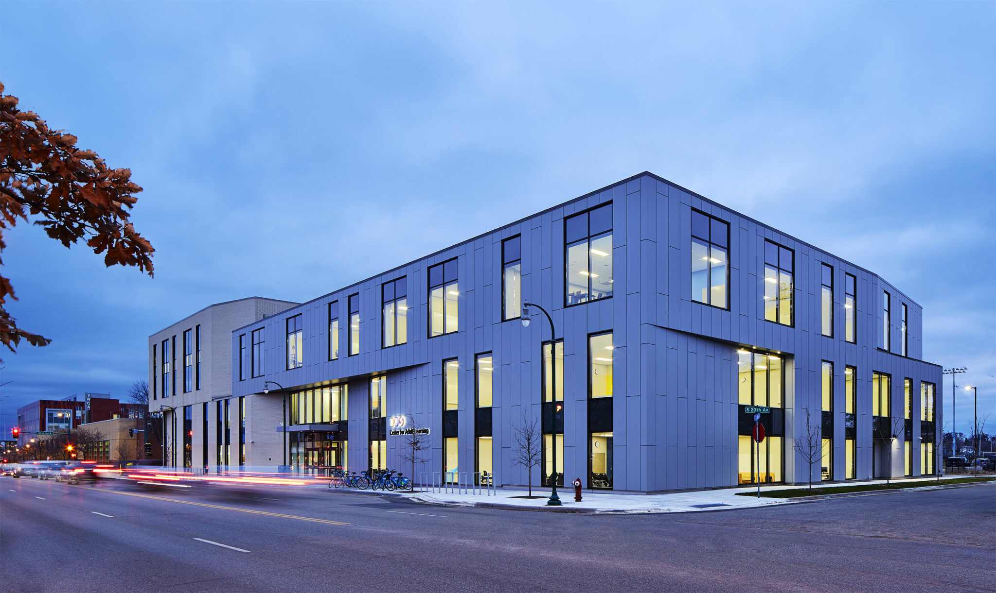
When a facade package includes mixed panel sizes, a fixed clip interval pulled from a standard detail sheet produces a clip count that does not survive contact with the actual panel schedule. The error compounds: wrong clip count means wrong material takeoff, wrong labor hours and a bid that either loses margin or loses the job. The calculation starts with panel geometry, not a grid assumption.
Aspect Ratio Sets the Structural Demand Before Any Other Variable
Aspect ratio, in the context of facade panels, is the ratio of the long edge to the short edge. A tall narrow panel and a wide shallow panel of identical square footage behave differently under wind load and thermal movement. The narrow panel has a longer unsupported span in one direction, which increases mid-span deflection under lateral pressure. The shallow panel distributes that same load across a shorter span and deflects less.
This distinction matters because deflection limits, not panel area, drive clip spacing requirements. The controlling variable is the long-span dimension. When that span exceeds the allowable interval for a given design wind pressure, clips must be added to bring mid-span deflection within the limits established by the applicable structural performance criteria. ASTM E330 governs structural performance testing for exterior wall systems under uniform static air pressure, and clip spacing that satisfies deflection limits under that protocol is the engineering basis for any defensible clip schedule.
The practical consequence is direct: two panels with the same square footage but different proportions will require different clip schedules. A takeoff that treats them identically will be wrong on both, either over-clipping the compact panel or under-clipping the elongated one.
A Fixed Clip Interval Is an Approximation, Not a Calculation
The common estimating shortcut is to apply a standard clip interval across the entire facade regardless of panel dimensions. It works well enough when the panel schedule is uniform. On a mixed-panel facade, it is an approximation that carries real risk in both directions.
The first failure mode is over-clipping on short-span panels. Clips added beyond what the geometry requires are material and labor cost that was not in the bid. The second failure mode is more serious: under-clipping on high-aspect-ratio panels creates a deflection condition that may not pass submittal review or field inspection. Neither failure is visible at bid time. Both surface later.
Submittal reviewers, including the structural engineer of record and the facade consultant, are increasingly checking clip schedules against panel geometry rather than accepting a standard interval at face value. A clip schedule that cannot be reconciled with the panel schedule during submittal review generates a revision cycle. That cycle costs time, and depending on where fabrication stands, it can cost material as well. An estimate built on a fixed grid creates exactly this exposure, and it surfaces after the bid is won, when the leverage to correct it without cost impact is lowest.
Converting Panel Geometry to Clip Count, Step by Step
A geometry-based clip count follows four steps that can be applied to any panel schedule before the bid is final.
- Extract the panel schedule from the drawings and sort panels by aspect ratio, not by zone or elevation. Group them into bands: 1:1 to 1.5:1, 1.5:1 to 2.5:1 and above 2.5:1. Banding allows the clip schedule to be applied by group rather than recalculated panel by panel, which keeps the process manageable on large facades.
- For each band, identify the controlling span dimension, the long edge, and apply the manufacturer’s maximum clip spacing for that span under the project’s design wind pressure. This produces a maximum allowable clip interval for each band. Design wind pressure is a project-specific value derived from ASCE 7 load combinations and the building’s exposure category. The clip spacing calculation is only as reliable as the wind pressure input, so confirm that figure from the structural drawings before finalizing the clip schedule.
- Calculate clips per panel using the panel perimeter and the allowable interval, accounting for corner clips and edge conditions. Sum by band, then total across the facade.
- Convert clip count to labor hours using a verified installation rate. If the installation system allows multiple crews to work simultaneously, those hours can be distributed across the schedule without changing the total count. A non-sequential installation system, where any crew can work any section in any order, is useful here because it prevents labor concentration on complex panel zones from holding up adjacent work.
High-Aspect-Ratio Panels Carry Disproportionate Labor Cost
The relationship between aspect ratio and clip count is not marginal. A panel with a high aspect ratio may require significantly more clips per square foot of facade area than a compact panel of the same size, depending on span and design wind pressure. On a mixed-panel facade, that difference accumulates quickly.
Labor hours do not scale linearly with clip count. High-aspect-ratio panels are also more likely to require intermediate horizontal clips at mid-span, which adds a handling and alignment step that a clip-count multiplier does not capture. The crew sets the panel, checks alignment, installs the field clips, then returns to install the intermediate clip at mid-span. That sequence takes longer per panel than the clip count alone would suggest.
The bid risk is concrete: a facade package with a significant share of its area in high-aspect-ratio panels can carry a disproportionate share of the total clip labor. Estimators who do not segment by aspect ratio will misallocate those hours across the panel schedule and produce a labor total that does not reflect where the time actually goes.
On projects where schedule is a constraint, the Arrowhead non-sequential installation system allows crews to work high-aspect-ratio panel zones independently of adjacent zones. Because panels install in any order, labor concentration on complex panels does not create a bottleneck that delays the rest of the facade. Other crews continue working without waiting on that zone to complete.
The Clip Count Is Always Higher Than the Field Calculation Suggests
Several categories add clips beyond what the field calculation produces, and each one is predictable if you account for it in the takeoff.
Corner clips at panel edges, clips at penetrations and reveals, clips at transitions between panel types and clips at the perimeter of the facade where wind uplift is highest all add to the total. The perimeter effect is the most significant. Under ASCE 7, component and cladding pressure coefficients distinguish between field, edge and corner zones. Corner and edge zones carry higher design pressures than field zones, which tightens the allowable clip interval and increases clip density at building corners and along the roof line. A takeoff that applies a single clip interval across the entire facade ignores this distinction and will undercount clips in the zones where they are most concentrated.
A zone-based approach addresses this directly. Calculate clip density separately for field, edge and corner zones using the pressure coefficients from the structural drawings, then sum across zones. The result is a more accurate total and a more defensible bid. Clip schedules that do not reflect ASCE 7 zone distinctions are not consistent with the structural basis of design and will be flagged during submittal review.
The Clip Schedule Is a Bid Document, Not a Shop Drawing Detail
The clip schedule produced during estimating does not need to be a final engineering document. It does need to be internally consistent with the panel schedule, the wind pressure assumptions and the installation system being specified. That internal consistency is what allows it to survive contact with the shop drawings.
The documentation chain is straightforward. Your clip count feeds the material takeoff. The material takeoff feeds the subcontractor scope. The subcontractor scope is what gets compared against the shop drawings during submittal. A gap between the estimate and the shop drawings is a change-order risk that could have been quantified before the bid was submitted.
Factory-finished panels with consistent dimensions and tolerances reduce the field adjustment rate, which is the variable that most often inflates actual clip count above the estimated count. Panels that arrive within tolerance install to the clip schedule as calculated. Panels that require field adjustment introduce unplanned handling steps that add labor hours outside the estimate. Vitrabond FR and Vitraplate ship factory-finished from Fairview’s Connecticut facility, and complete technical documentation, including panel tolerances and installation details, is available before commitment. Having that data during estimating rather than after award allows the clip schedule to be built on actual product dimensions rather than assumed ones.
Retain the clip schedule as a bid backup document and reconcile it against the shop drawings when they are issued. Differences of more than 5 percent in total clip count warrant a scope review before fabrication begins.
A Defensible Clip Count Starts With the Panel Schedule, Not the Detail Sheet
Panel aspect ratio is the variable that drives clip spacing, and clip spacing drives both material cost and labor hours. An estimate that skips this step carries unquantified risk that will surface during submittal, fabrication or installation, at a point when correcting it costs more than calculating it correctly would have.
Facade packages with mixed panel sizes reward estimators who segment by geometry. The framework here, aspect-ratio banding, zone-based pressure adjustment and a documented clip count reconciled against shop drawings, produces a number that can be defended through submittal and held through the project.
Confidence in a facade bid comes from the same place as confidence in a facade system: documentation, verified dimensions and a calculation that can be traced back to its inputs.
Fairview’s technical team can provide panel dimension tolerances, installation details and clip spacing guidance for Vitrabond FR and Vitraplate before your bid is final. Request the technical package at fairview-na.com or call 860-242-2711.