
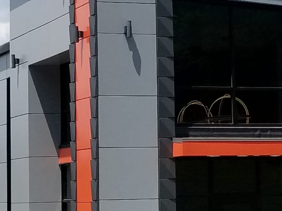
You have specified an air barrier, confirmed your drainage plane and detailed your cavity depth, but the joint geometry on your panel layout sheet may still be working against you. Pressure equalization is not a property of the wall assembly as a whole; it is a condition that must be achieved at each individual joint, through deliberate geometry and compartmentalization. If that distinction is not embedded in your construction documents, the physics will find the gap.
The Joint Is the System, Not the Cavity
Pressure equalization at the joint means one specific thing: the air pressure immediately behind the joint opening must equal the air pressure at the exterior face of that joint before water can be driven inward. That condition is distinct from drainage, and the distinction matters more than most commercial specifications acknowledge.
A drained joint relies on gravity and clear drainage paths to remove water that has already entered the assembly. A pressure-equalized joint prevents water entry by eliminating the pressure differential that would drive it inward. Most commercial rainscreen specifications conflate the two, which creates a wall assembly that drains adequately under moderate conditions but admits water under dynamic wind loading.
The cavity depth behind the panel is a supporting condition, not the equalization mechanism. Equalization occurs at the throat of the joint, where exterior pressure and cavity pressure must converge. Wind-driven rain creates a dynamic pressure differential measured in pascals; without equalization at that throat, the differential becomes the driving force for water ingress regardless of how well the cavity is detailed behind it.
AAMA 508-07, the voluntary test method for pressure-equalized rainscreen wall systems, defines performance criteria at the joint level and requires compartmentalization as a precondition for test compliance. That requirement is not incidental. It reflects the physics of where equalization must occur.
Compartmentalization Is What Makes Equalization Possible
A pressure-equalized joint cannot function without a bounded compartment behind it. If air moves freely across the entire cavity plane, pressure cannot stabilize because there is no discrete volume to equalize. Compartmentalization divides the cavity into sealed segments, typically defined by horizontal and vertical baffles or by the geometry of the panel attachment system itself, that allow pressure within each segment to equalize to the exterior condition through the joint opening.
Compartment sizing is not arbitrary. An oversized compartment increases the volume of air that must equalize and slows the response time under dynamic wind loading. A compartment that is too small may be difficult to construct consistently and may not align with the panel grid at corners and terminations. The compartment geometry must be resolved during design development, not left to the installer to interpret in the field.
One persistent detailing error is treating the continuous air barrier as the compartmentalization layer. The air barrier controls vapor diffusion and bulk air movement at the substrate. It operates at a different plane and serves a different function than the baffles that define the pressure compartment at the joint. ASTM E2357, the standard test method for determining air leakage of air barrier assemblies, evaluates the substrate assembly independently; it does not validate joint-level pressure equalization. Passing ASTM E2357 confirms that the air barrier performs at the substrate. It says nothing about whether the joint equalizes.
Joint Width, Depth and Profile Determine Whether Equalization Happens Fast Enough
Even a correctly compartmentalized system can admit water if the joint geometry impedes equalization rate. Equalization rate is the speed at which pressure behind the joint reaches equilibrium with exterior pressure. A joint that equalizes too slowly still admits water during the pressure differential window, particularly under gusting conditions where the differential fluctuates rapidly.
Joint width controls the area through which air can enter and exit the compartment. A joint that is too narrow restricts airflow and slows equalization. A joint that is excessively wide reduces the capillary resistance that limits water entry under low-pressure conditions. The design width must balance both considerations and must account for the full range of in-service conditions including thermal movement.
Joint depth, meaning the distance from the panel face to the back of the joint cavity, affects the pressure gradient along the water entry path. A shallow joint with no baffle creates a direct path from the exterior to the compartment. A deeper, baffled joint forces water to change direction before it can reach the compartment interior, which reduces the kinetic energy available to drive it further inward.
Joint profile geometry, whether the joint is open, baffled or labyrinthine, must be coordinated with panel thickness and attachment system depth during design development. Resolving these relationships during shop drawing review is too late; by that stage, the panel dimensions and attachment grid are fixed and the options for adjusting joint geometry are limited.
Vitrabond FR aluminum composite panels are available in panel thicknesses and edge configurations that support baffled joint detailing. The panel edge geometry is a design variable that can be coordinated with joint strategy from the start of design development, not a fixed constraint that forces the joint detail to accommodate whatever arrives on site.
A Continuous Air Barrier Supports Equalization but Does Not Replace It
The air barrier and the pressure-equalized joint are complementary systems that operate at different planes and address different failure modes. The air barrier limits the volume of air that can bypass the joint and enter the building assembly, which stabilizes the pressure differential the joint must equalize. That is a supporting function. The equalization mechanism itself is the joint geometry and the compartment behind it.
Relying on air barrier continuity to compensate for inadequate joint geometry is a specification risk that is easy to overlook because both systems are often addressed in the same wall assembly specification section. If the joint does not equalize, water enters the compartment regardless of how well the air barrier performs at the substrate.
Air barrier transitions at penetrations, corners and terminations are the locations where both air barrier continuity and joint geometry are most likely to be compromised simultaneously. These are the same locations where panel attachment conditions change, where compartment geometry is most difficult to maintain and where the consequences of a detailing gap are most likely to produce a water management failure.
ASHRAE 90.1 requires continuous air barriers in commercial construction and references ASTM E2357 for assembly testing. Compliance with 90.1 addresses energy performance and air leakage at the assembly level. It does not address rainscreen joint pressure equalization as a water management criterion. The two obligations are related but not interchangeable, and a specification that satisfies one does not automatically satisfy the other.
Sequencing matters. Construction documents should specify the order of air barrier installation and panel attachment system installation explicitly. Field conditions that allow the attachment system to be installed before air barrier transitions are complete at penetrations and corners are a predictable source of compromised performance in both systems.
Panel Selection and Attachment System Must Be Coordinated with Joint Strategy from the Start
The decision points where panel geometry, attachment system depth and joint strategy must be resolved together follow the design phase sequence. Cavity depth is a schematic design decision. Joint profile and compartment layout are design development decisions. Baffle detailing, tolerances and sequencing requirements belong in the construction documents. Deferring any of these to a later phase compresses the coordination window and increases the likelihood of conflicts that cannot be resolved without redesign.
Aluminum composite panels and solid aluminum panels have different edge conditions and stiffness characteristics that affect how joint geometry is maintained under thermal movement and wind load. The joint must perform across the full range of in-service conditions, not only at installation when everything is plumb, square and at the mean temperature. Thermal expansion and contraction will open and close the joint; the design width must account for that range so the joint does not close below the minimum equalization threshold or open beyond the capillary resistance threshold at any point in the service life.
Architectural finish systems must be specified to maintain performance at the panel edge and in the joint zone, where UV exposure and moisture cycling are most concentrated. AAMA 2605 is the specification standard for high-performance organic coatings on architectural aluminum. Coatings meeting AAMA 2605, including PVDF systems, are required to demonstrate resistance to humidity, salt spray and weathering at panel edges. In a baffled joint condition, the panel edge is an exposed surface, and finish performance at that edge is a functional requirement, not an aesthetic one.
The Errors That Undermine Pressure Equalization Are Detectable Before Construction
The four most common detailing errors in pressure-equalized rainscreen joint design appear in the following order of frequency:
- Omitting compartmentalization baffles from the detail set entirely, leaving equalization undefined and dependent on conditions that will not produce it
- Specifying compartment dimensions that are inconsistent with the panel grid, creating oversized or undersized compartments at corners and terminations where the grid changes
- Detailing the air barrier as the compartmentalization layer without acknowledging that the two systems operate at different planes and serve different functions
- Failing to coordinate joint width tolerances with the thermal expansion range of the panel material, which can close or open joints beyond the design condition during service
A checklist review at the 90 percent CD stage that cross-references joint details against compartment layout drawings and air barrier termination details will catch most of these conflicts before they reach the field. The review should confirm that baffle locations are shown in plan and section, that compartment dimensions are dimensioned consistently with the panel grid and that air barrier termination details at penetrations and corners are coordinated with the attachment system layout.
Facade peer review or envelope consultant engagement at the design development stage is the most cost-effective point to identify and resolve these conflicts. IBC Chapter 14 requires exterior wall coverings to resist wind and water penetration; while it does not prescribe pressure-equalized joint design, it establishes the performance obligation that joint-level equalization is designed to meet. Meeting that obligation requires the joint to be engineered, not assumed.
Getting the Joint Right Is How You Build with Confidence
Pressure equalization is not a wall assembly property that emerges from specifying the right products in combination. It is a condition that must be engineered at the joint, supported by compartmentalization geometry, coordinated with the air barrier and maintained across the thermal and wind load range the facade will experience in service. The products matter, but they perform only within a detail set that gives them the conditions they require.
If you are working through joint geometry on a current project or reviewing a specification that conflates drained and pressure-equalized performance, Fairview’s technical team can support that process. Whether you need detail review, product geometry information for Vitrabond FR or a conversation about how panel selection coordinates with joint strategy, the starting point is a direct conversation with someone who works through these details regularly. Reach out to request a spec consultation or a sample set that lets you evaluate edge conditions and finish performance in the context of your project.